Building a dual fast Pulse Generator
Or rather combining two generators into one cabinet.
I had an S-52 and a 067-1338-01 that I wanted to have a better access to. I also had a NOS Vector Scope Test Unit that was totally useless to me mostly because analog
TV is no more and also it was NTSC. It was enclosed in the same cabinet as the old scope calibration generators 067-0502-01, 184 and 191. I figured this cabinet could be
used for this project.
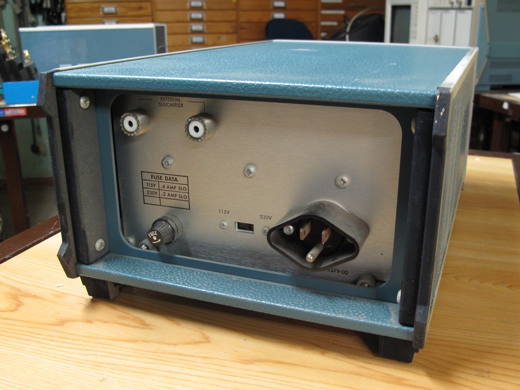
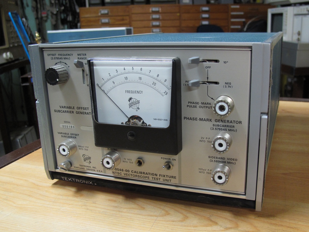
The original Vector Scope Test Unit
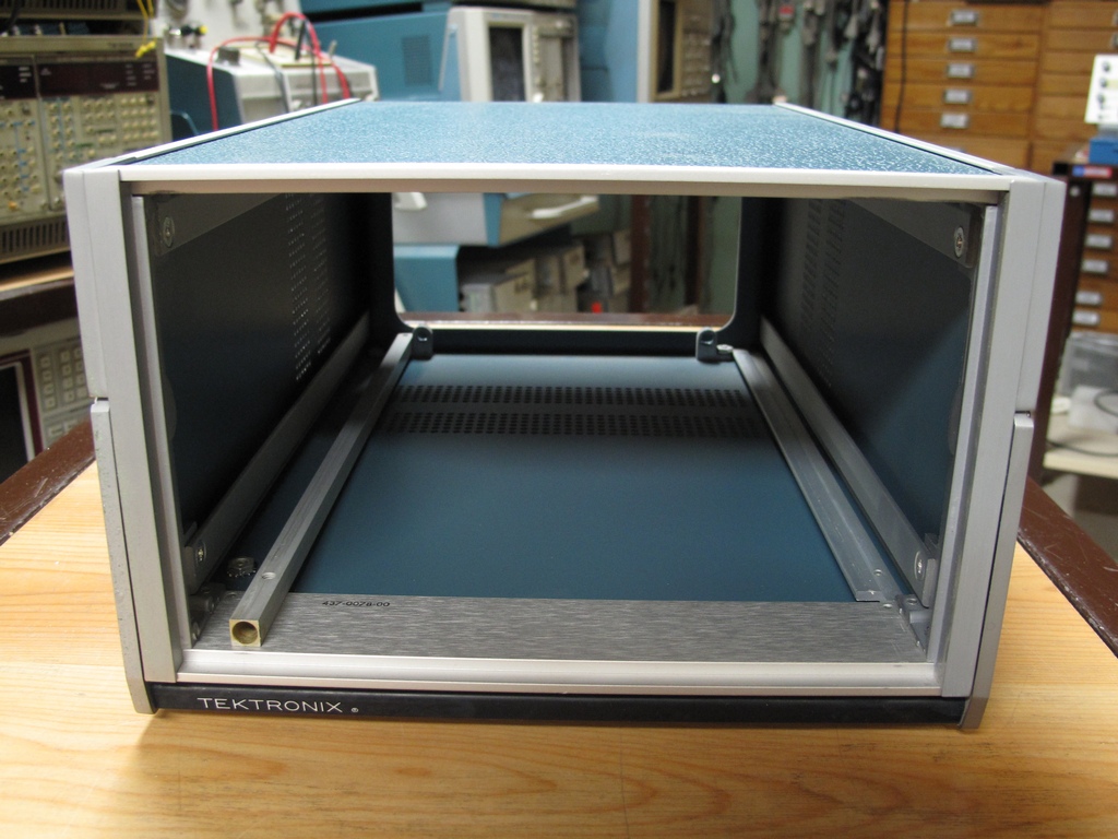
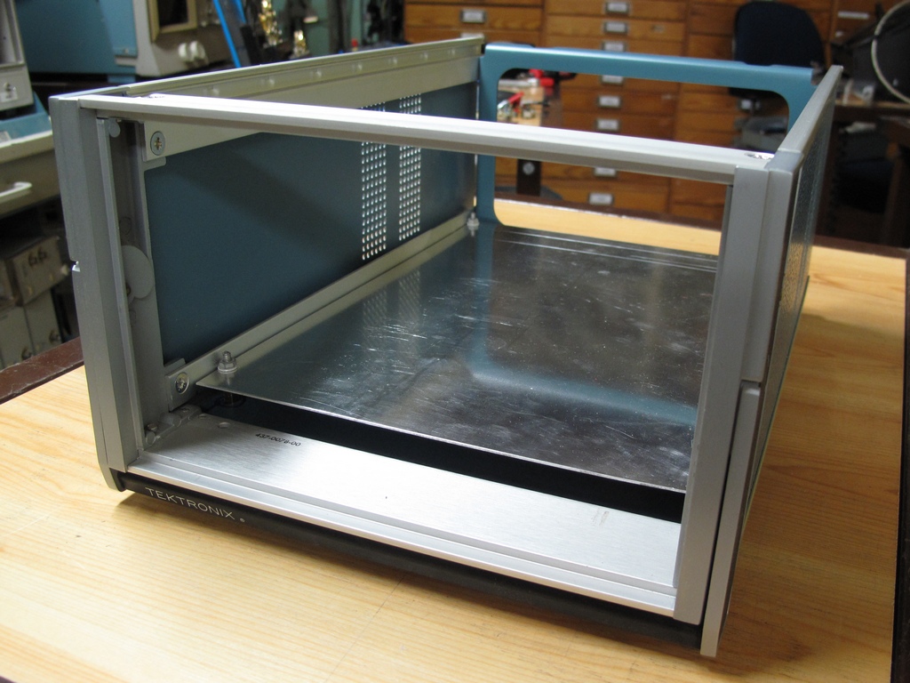
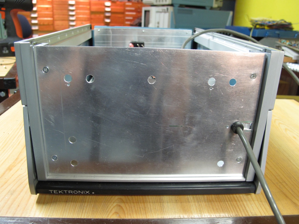
The cabinet with the Test Unit removed. The guides on the left and right were removed and later reused for other purposes. The two guides with holes seen at
the rear was the only things from the cabinet I didn't use.
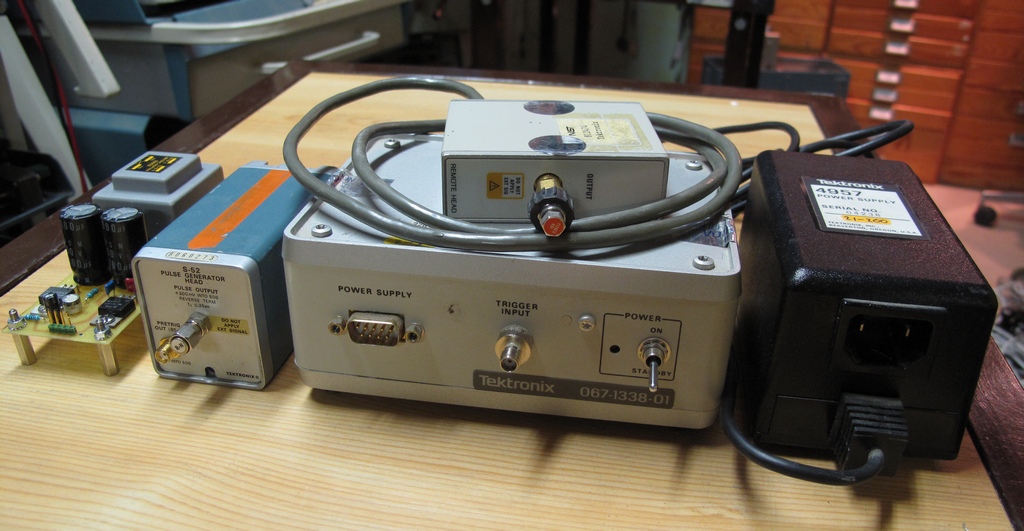
These are the things I wanted to put into the box. The far left is a special built power supply for the S-52 (+15V and -12.2V). The Pre Trig connector on the S-52
has been replaced by an SMA connector.
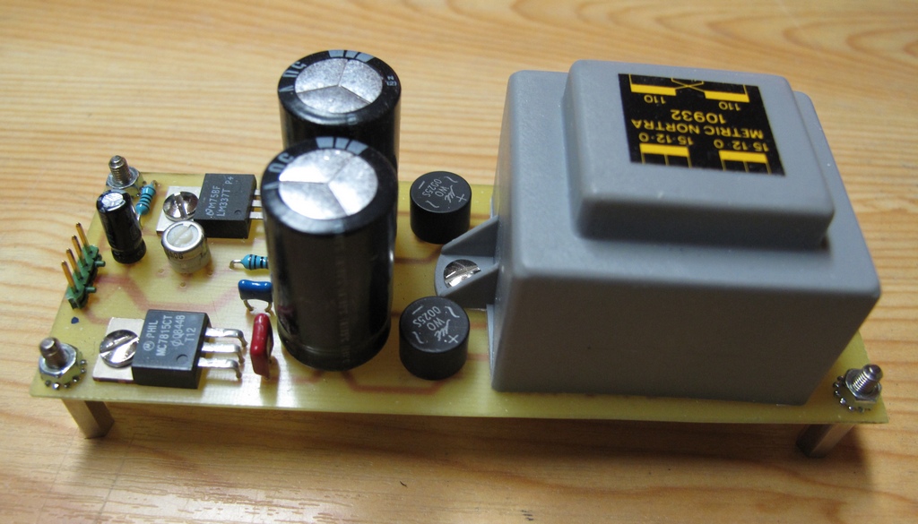
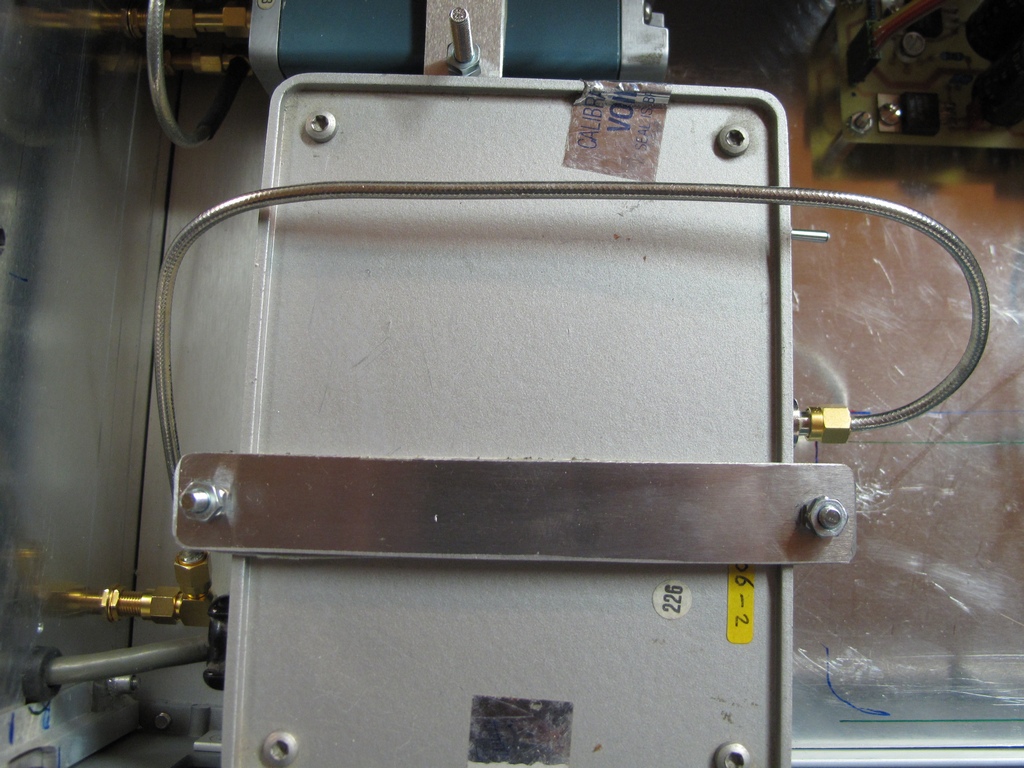
Close up of the special P/S. I could have made a similar P/S for the 067-1338-01 too but I didn't want to take a risk of screwing up and damage the rare and
expensive generator so I figured it would be safest to keep the original.
Made a new sub frame of aluminum attached to the original holes of the feet using longer screws and threaded stand off's.
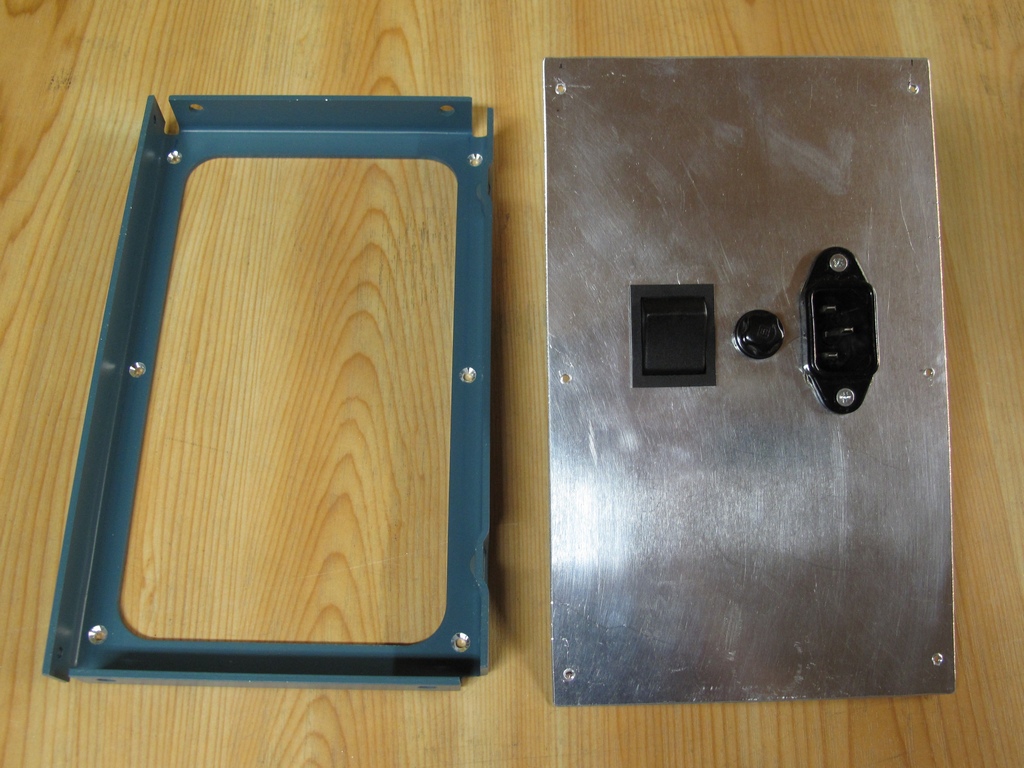
Made a new rear panel, with AC connector, fuse holder and AC switch, to be attached to the original rear frame.
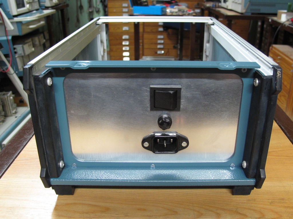
The fished rear panel.
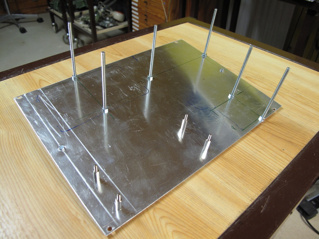
The sub frame with mounting screws for all the components in place.
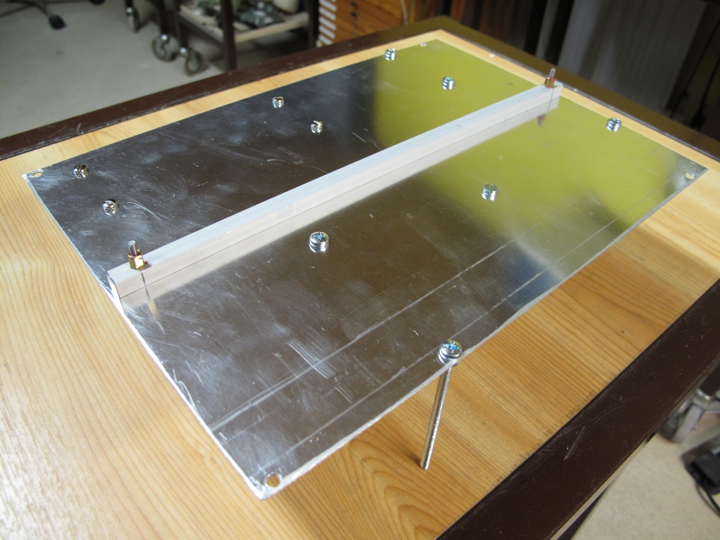
On the the reverse side of the sub frame I used one of the guides shown on pic 3 together with a pair of short stand off's to prevent the whole thing from flexing.
Made the front panel in two pieces. The one shown here is attached to the cabinet with the other guide which was split in half first, see next pic.
The other (not shown) was made with 0.5 mm aluminum and is a copy oft his one except for the four screw holes in the corners. It is held in place by the switches
and connectors.
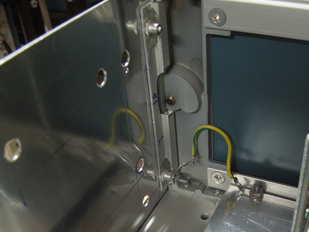
The brackets holding the frontpanel made from the other guide.
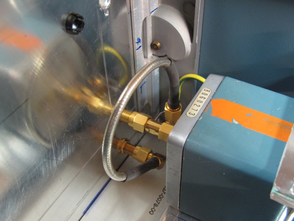
The S-52 connected to the front panel.
The 067-1338-01 Trig Input connected to the front panel.
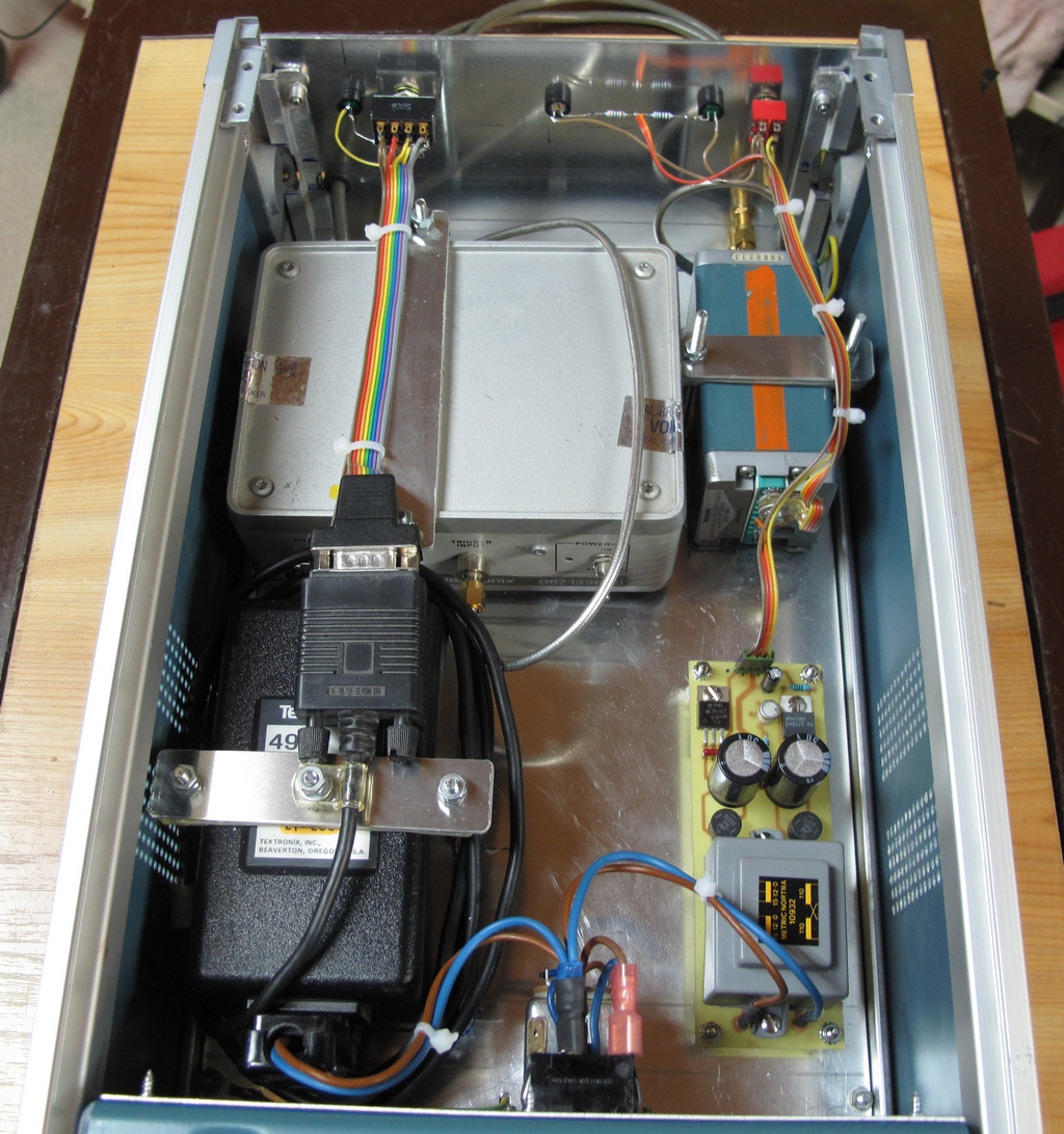
The inside of the finished box.
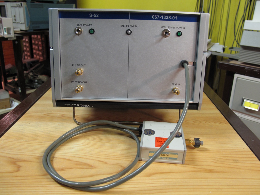
The front of the finished box. The lettering on the front panel was designed with MS Word and printed on a Self-Adhesive film from Letraset and applied to the
thin aluminum panel.
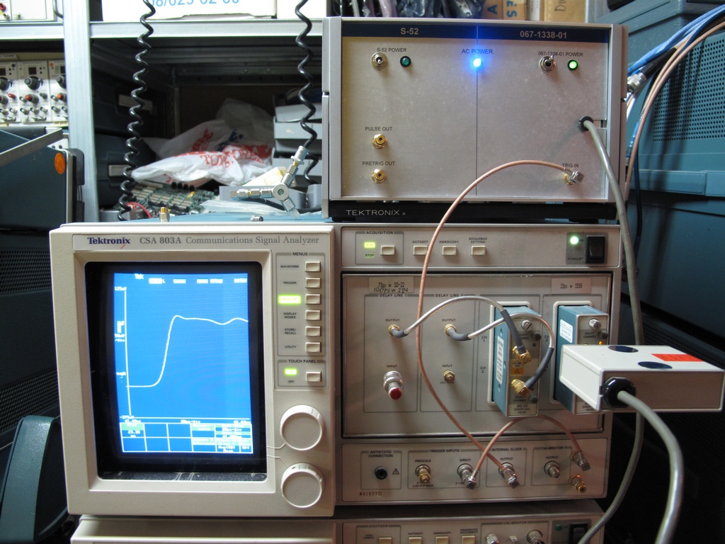
The 067-1338-01 connected to my CSA803A. Someone may say that the CSA803A looks strange which is correct. It uses the Acquisition Module with delay lines
from an 11802. The two added SMA connectors on the lower right are Trigger Pick Off's from the delay line. As connected on the picture the CSA will trig
"internally" on CH1 of the delay line if External Trig is selected. The 067-1338-01 uses the CSA clock so no trig is needed.
Unfortunately, when used, the delay line limits the rise time of the SD-22 to a little over 70 ps.
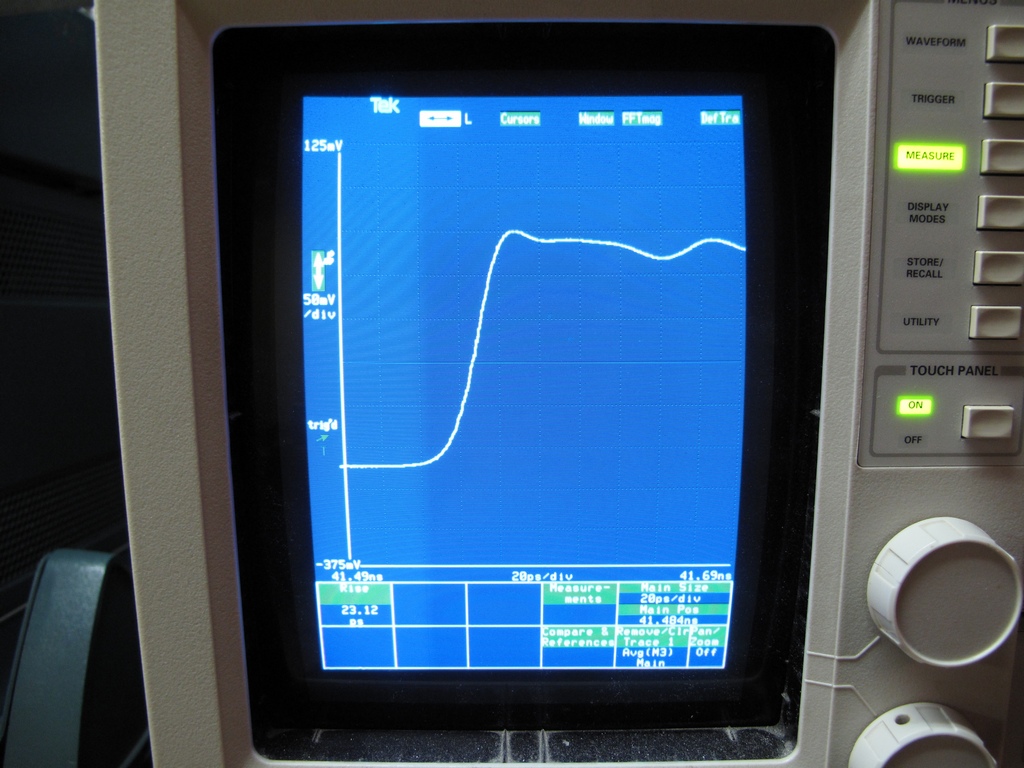
Close up of the Step Response. Assuming the SD-26 has the specified rise time of 17.5 ps and the CSA time base is ok the calculated rise time of the generator
will be approximately 15 ps.
Email me with comments. /Håkan
Home / Go back