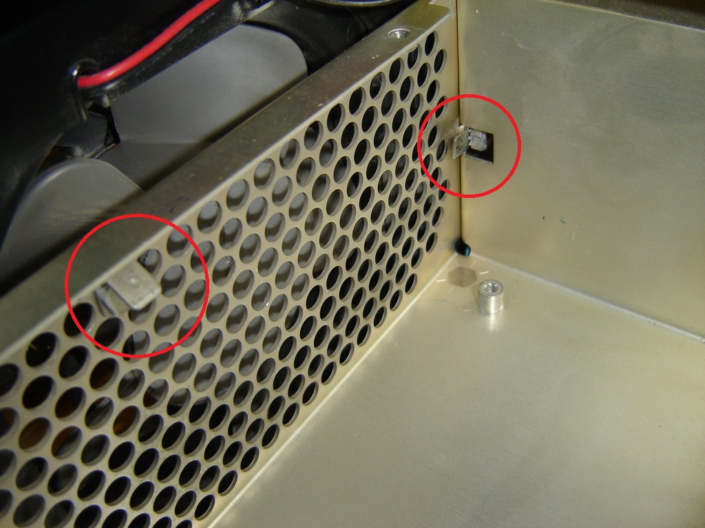
3: Add two new ground terminals inside the CRT driver compartment.
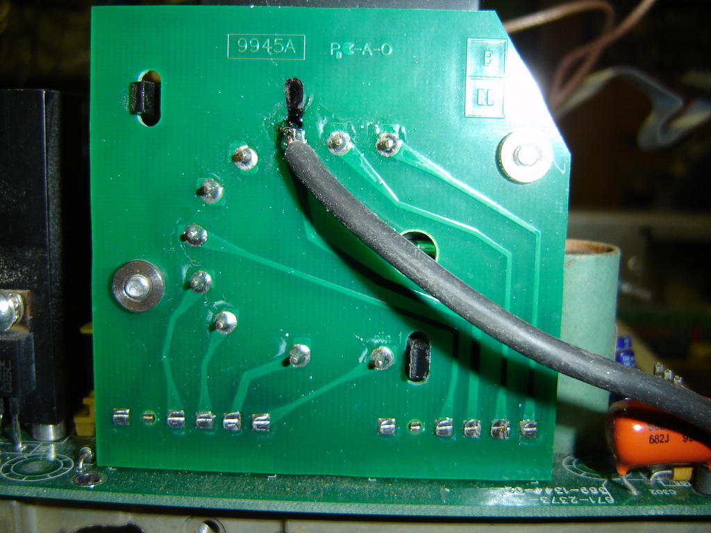
4: Add a wire to pin 8 of the HV transformer as seen on the picture. The length approximately 3.5” and with a flat pin connector on the other end.
5: Install the CRT driver assy back in the scope.
6; Connect the new wire from the HV transformer to the new ground connector on the rear.
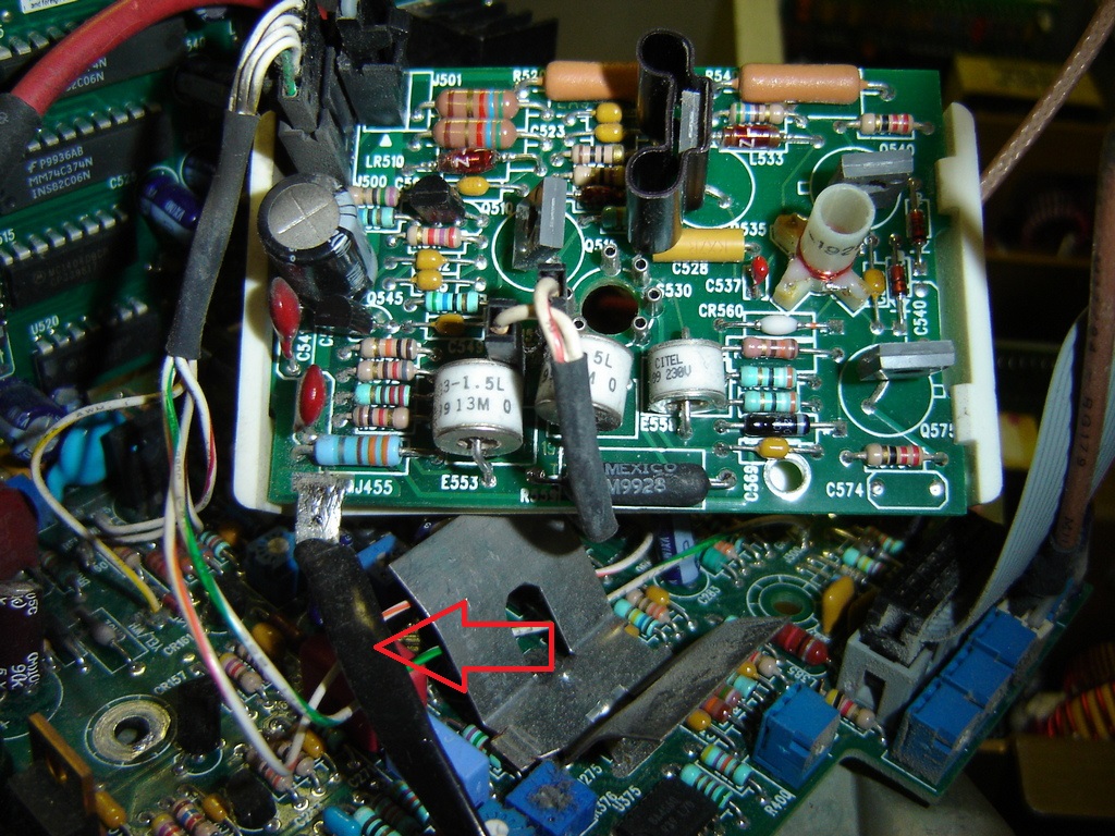
7: Move the ground wire on the CRT rear connector board from the connection on the large board to the new ground connector on the side
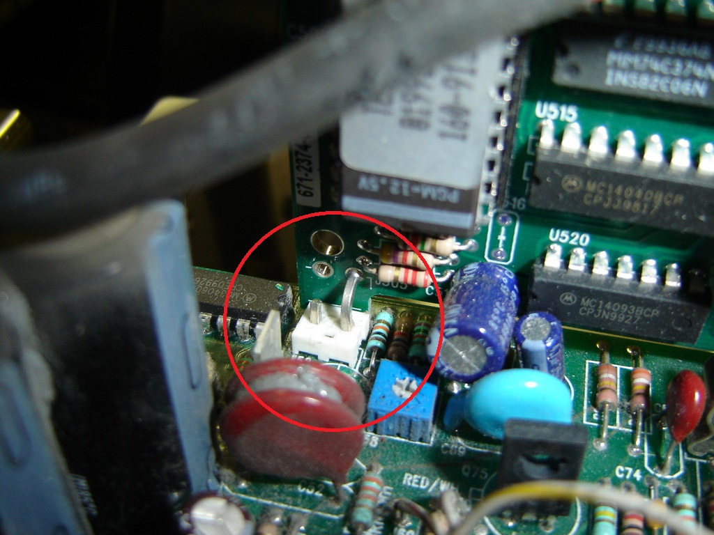
8: Replace the EPROM, 160-9137-00 on the Shutter board with 160-9137-02. The new has the same content but is a faster version: -00 = 27C64A-250 and -02 is 27C64A-20
9: Install the CRT and test.