Modifying 465 V/Div lights
I was fixing a broken 465 for a friend. As usual one of the faults was an burned out lamp in the scale factor switching circuit of one channel. Even though I had a couple
of NOS lamps I was curious about if the lamps could be replaced by LED's. Obviously they couldn't just replace the lamps directly so some modification was needed.
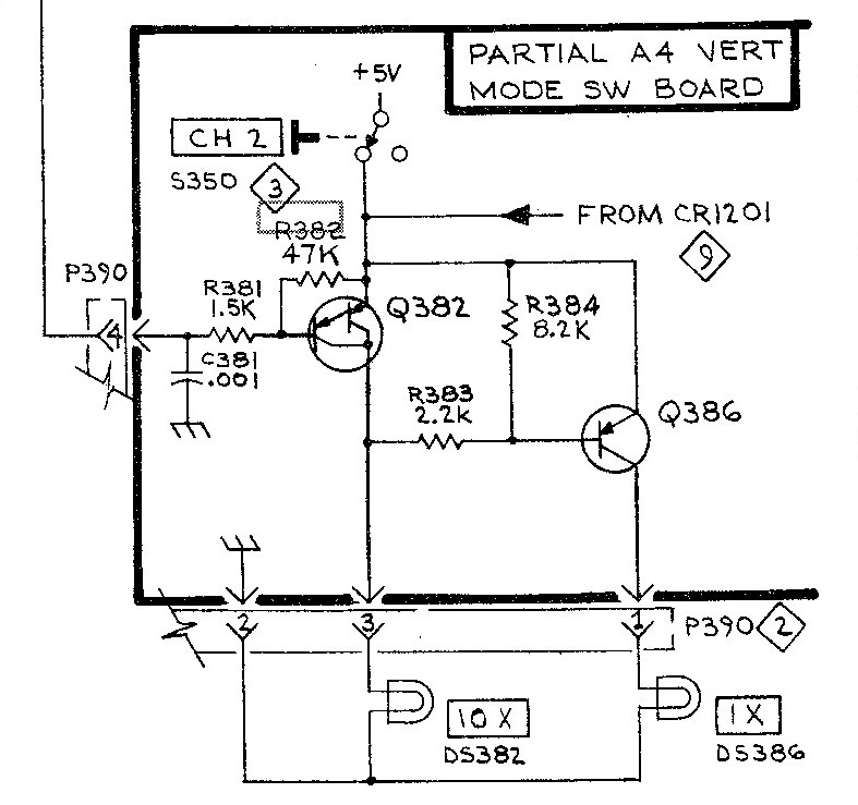
This is the original circuit. The bias on of Q386 is relying on a small current trough DS382 which is not enough to turn on the lamp. If the lamps were just
replaced by LED's this small current would be enough to slightly turn on the 10X LED while 1X is active.
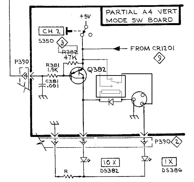
This is how I modified the circuit. I made a small piggyback PCB with just one reed relay and a protective diode on it. R283, R284 and Q386 were removed. The
PCB fitted in four of the holes vacated by the removed components. The only thing that had to done on the VERT MODE SWITCH BOARD was to connect ground
to the base hole of the removed Q386. A small resistor (R) had to be added in series with the ground wire to the LED's. The value of the resistor determines how
bright the LED will be. In my case with very bright white LED's about 1 mA was sufficient and the resistor value is 2.2k.
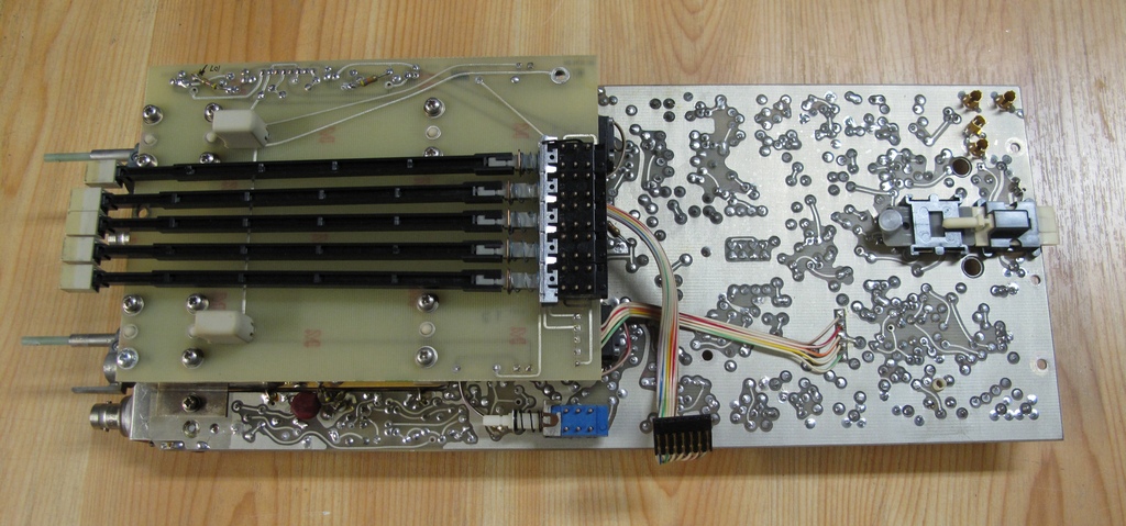
In order to get access to the lamp holders the whole Vertical Pre Amp board with Vertical Mode Switch Board has to be removed. It may look like a big deal if
you haven't done it before but in fact it's quite easy. There are two nuts in each attenuator and to get to those the cap for AC coupling has to be removed. Then
there are three screws and one stand-off with a ground spring. Several coax cables with Peltola connectors disconnect easily, make a note of their location so
they can be reconnected to the right place. The delay line has to be unsoldered at one ground connection and there are five wires that have to be unsoldered, one
on the main Vertical board close to the delay line, one on the Switch Board, one from each input BNC close to each attenuator and a ground connection below
the CH2 attenuator that connects to the Main board. The flat cable also has to be disconnected from the main board. It's a seven pin connector that connects
to eight pins so make sure it's correctly reconnected when done. Off course all knobs on the front panel also have to come off.
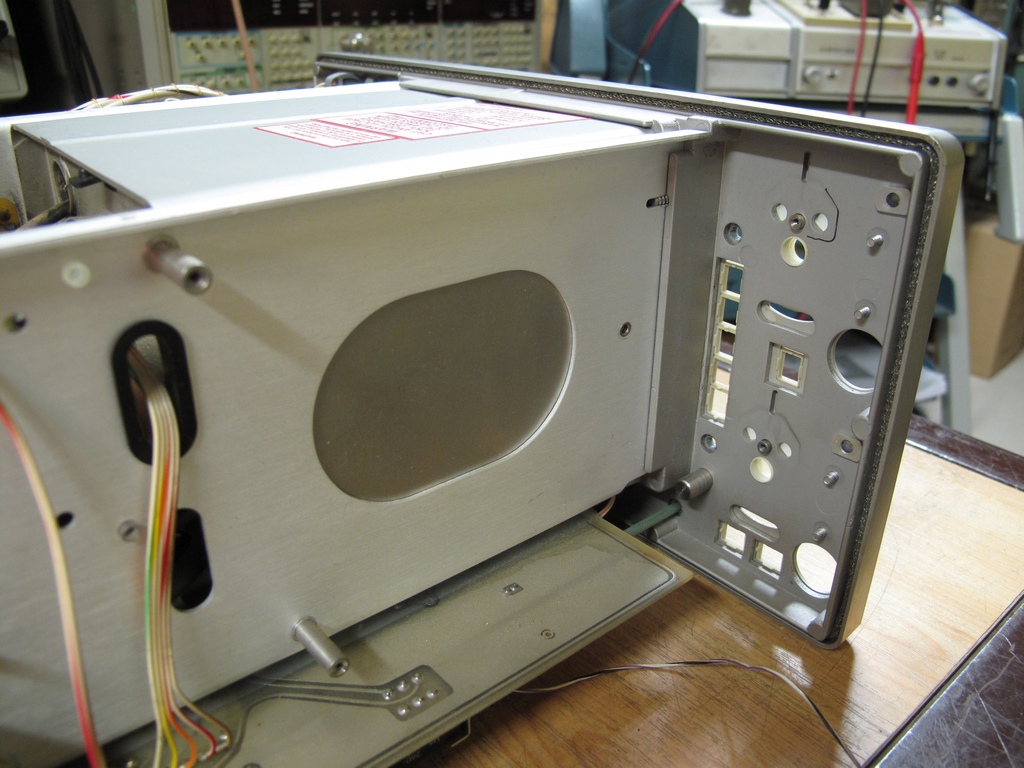
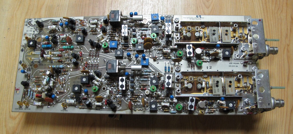
The inside of the scope with the boards and lamp holders removed.
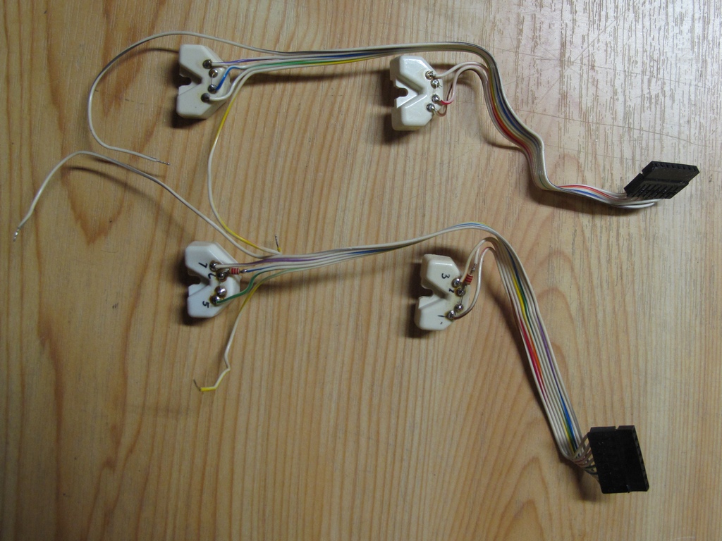
The original lamp holders at the top and the modified one at the bottom (note the added resistors).
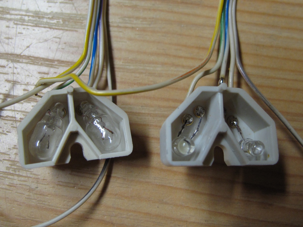
The inside of the lamp holders. Bulbs on the left, 3 mm white LED's on the right. There is a small circle in each cavity of the lamp holders and if the LED's are
placed just above them they will coincide exactly with the holes in the front panel.
The lamp holders with LED's installed.
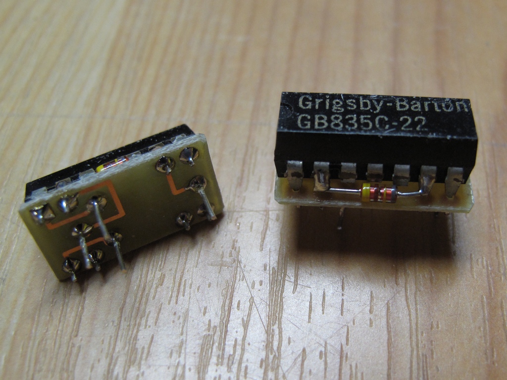
The two piggyback boards. Note that the diodes are mounted the wrong way in the picture, the cathode should be facing right..
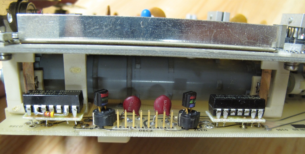
The two piggyback boards installed.
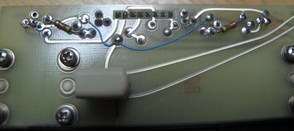
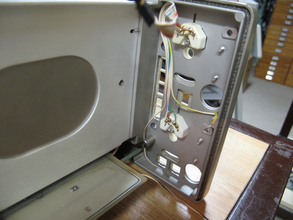
The rear of the Vertical Mode Switch Board showing the new ground wires.
Email me with comments. /Håkan
Home / Go back