SI 5010 power relays modification
I wanted a way to be able to switch higher DC currents via GPIB.
One option was to build an external switchbox controlled by an SI 5010. Another
was to modify an SI 5010 itself. Since I already owned 3 SI 5010's I went for
the mod.
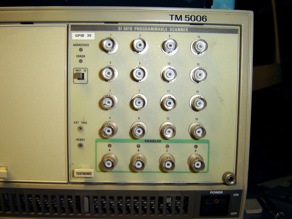
The SI 5010 is a TM5000 plug-in with 16 + 4 BNC connectors on the front panel.
It can be configured in several ways to switch 1 to 16, 2 x 1 to 8 or 4 x
1 to 4.
It was designed to switch frequencies up to a couple of hundred MHz's and not
more that 10 mA of DC.
The original SI 5010
After some thinking I decided to internally add 4 ea SPDT 12V car
relays driven by a custom made circuit board which in turn was controlled by +5V
via the
4 first original
SI 5010 reed relays.The car relays are rated 30A and to route the power to the front panel I
replaced 4 x 3 of the BNC's with banana sockets. That left
two rows of
connectors
unused so there I could put
LED's to indicate relay status and toggle switches so the relays could also be
activated manually.
The Front Panel:
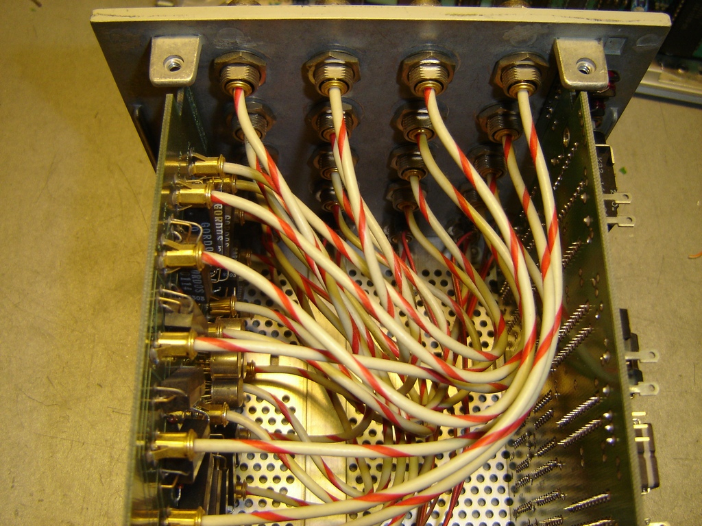
The original front panel from the inside
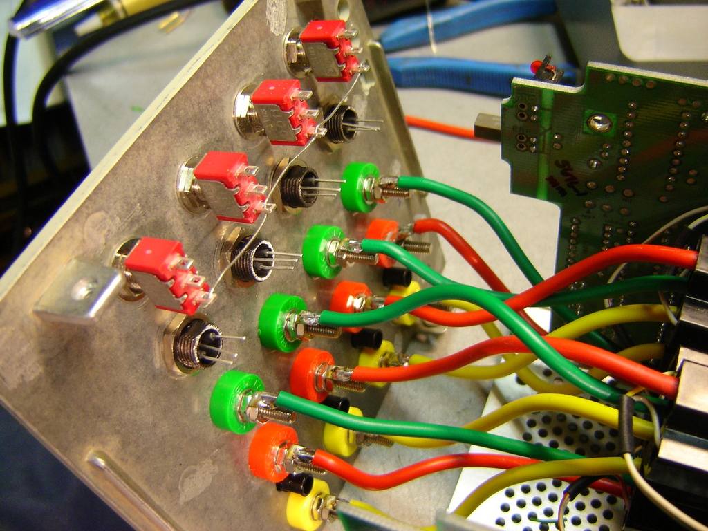
The modified front panel from the inside
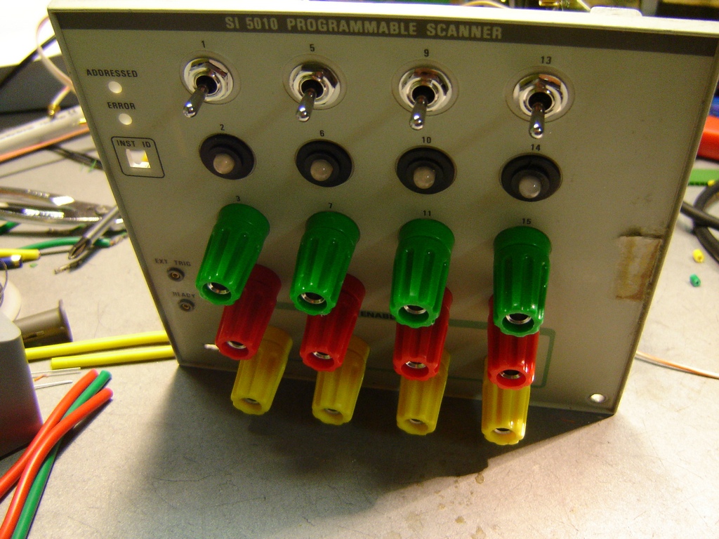
..... and from the outside.
The LED's are dual color (red and green) and the holders are actually the
BNC connectors with the center knocked out, sawed off and painted flat black.
The Relays:
The car relays were placed 2 by 2 on posts close to the front panel.
I used
the special sockets that came with the relays but had to move the wires around
so the colors would match the banana sockets.
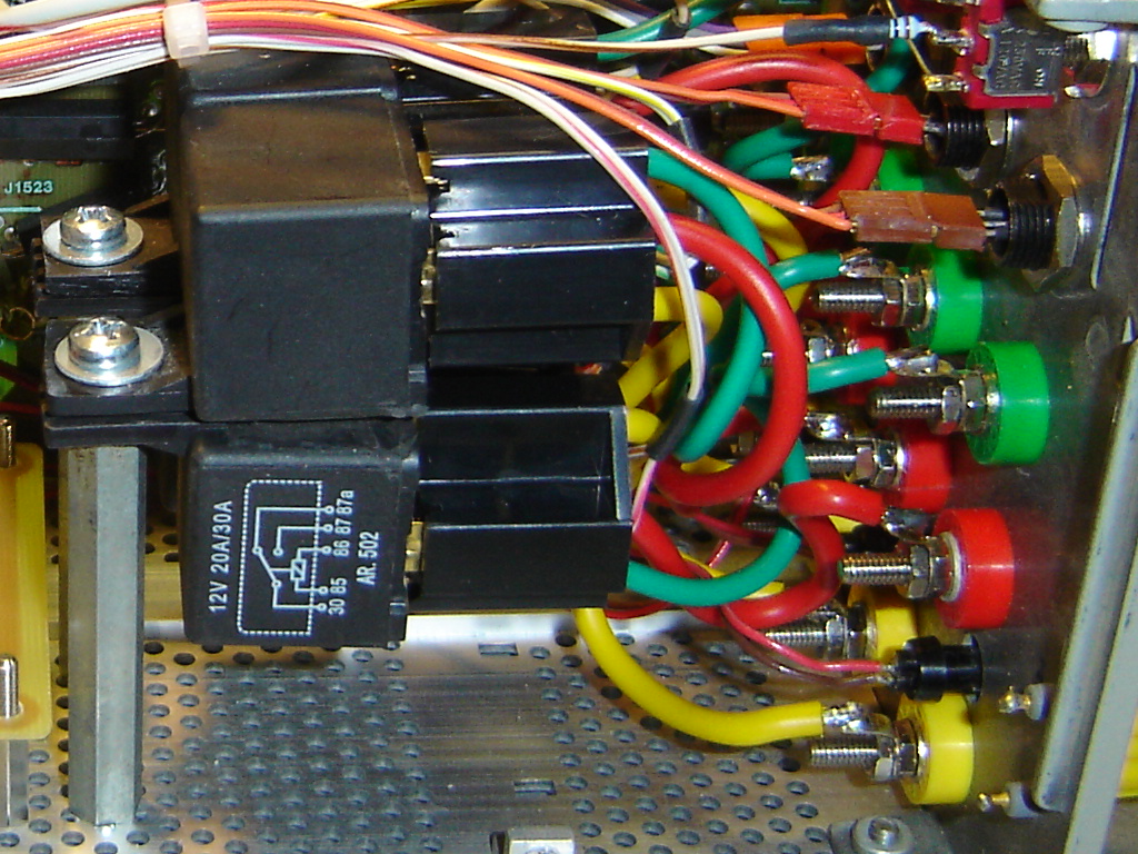
The 4 relays
The circuit board:
I designed and made a simple circuit board with 4 identical relay and LED
drivers. It also contained a power supply to convert down to 12 VDC from the
only suitable TM5000
power line found in the SI 5010 which is 25 VAC. I started experimenting with one
LM7824 and one LM7812. It had to be done in two steps since the input voltage
would
otherwise exceed the 7812 rating. However I soon found that it would generate too
much heat with all relays and LED's activated so I went for a DC-DC converter
instead which
generates almost no heat. The three serial power diodes are to lower the input
voltage to the DC-DC converter a bit which otherwise could be rather close to
the limit.
Schematics here.
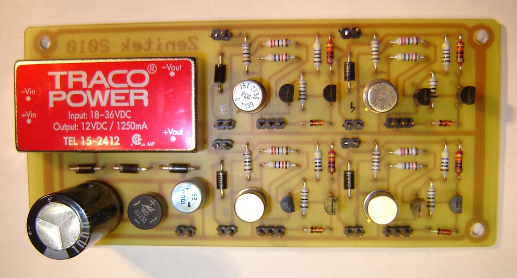
The circuit board
Mechanical:
I made the circuit board so existing air holes in the bottom frame could be used for mounting.
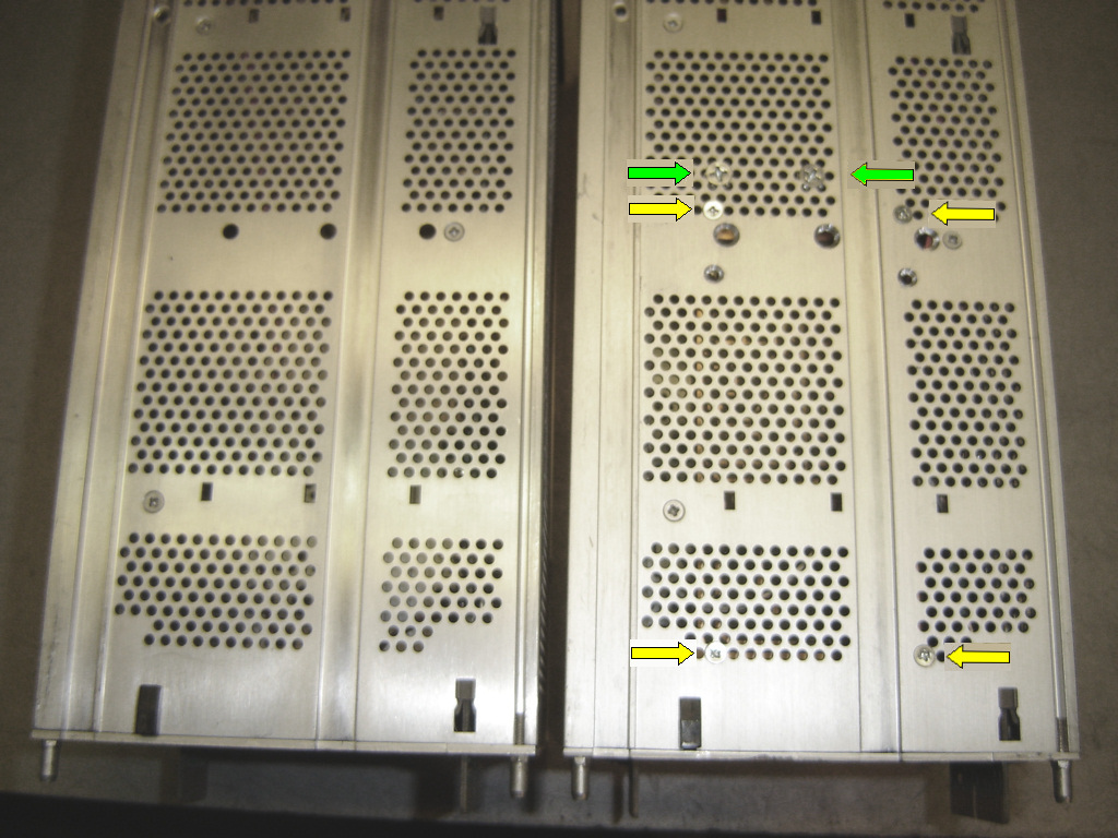
The original to the left and the modified to the right. Green arrows are
the posts holding the relays and the yellow arrows are the circuit board mounts.
The holes at the center are from experimenting with different location of the
relays and a different sized circuit board.
The final result:
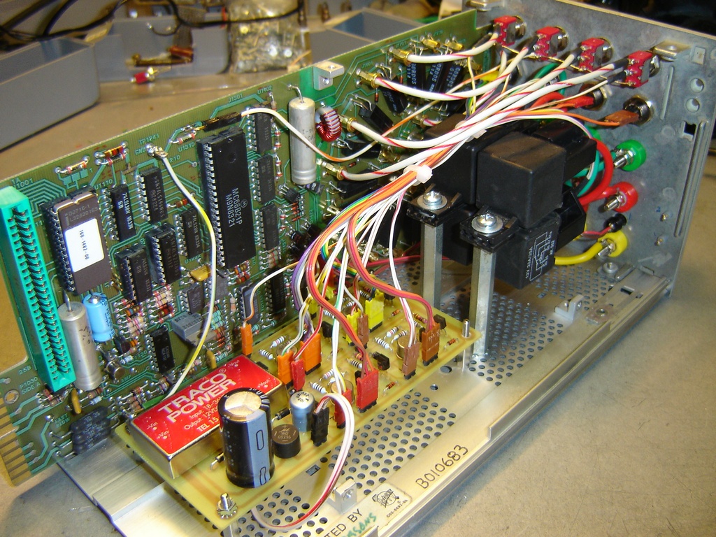
The circuit board, relays and wiring in place. The white/yellow wire is a
GND connection, the white/orange wire is +5V. The 25 VAC is taken from the lower
left of the large circuit board partially seen as a green connector just above
the DC-DC converter.
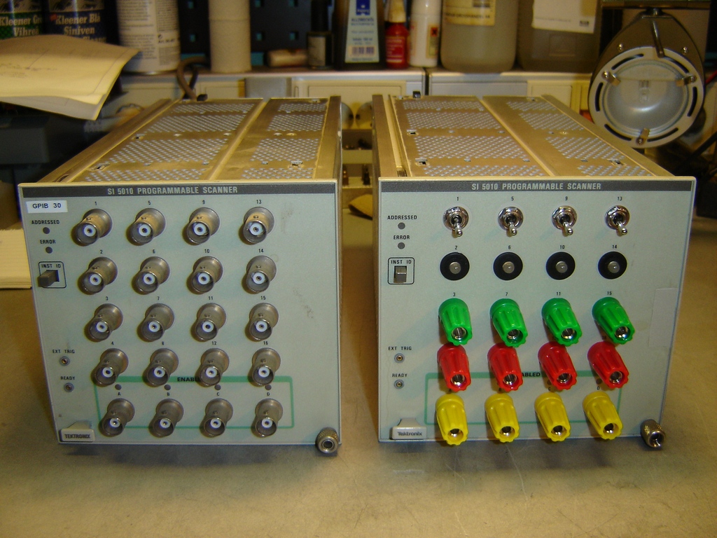
Comparing the original and the modified SI 5010

The finished modified SI 5010 in operation. The color of the LED's off course indicates which connector is currently connected to the yellow connector.
Email me with comments. /Håkan
Home / Go back