Modifying DC5010 EXT Clock Input
The DC5010 has the capability to use an external clock but it has to be selected by moving straps deep inside the instrument. Removing the side covers aren't enough, the
top frame also has to be removed to access the straps and that pretty much limits the use of this function to be either enabled or not. I wanted it to be selectable from the outside
so I could use my Frequency Standard (previously Rubidium, now GPS) when needed for high accuracy measurements and the internal (OPT 1) clock for everyday use.
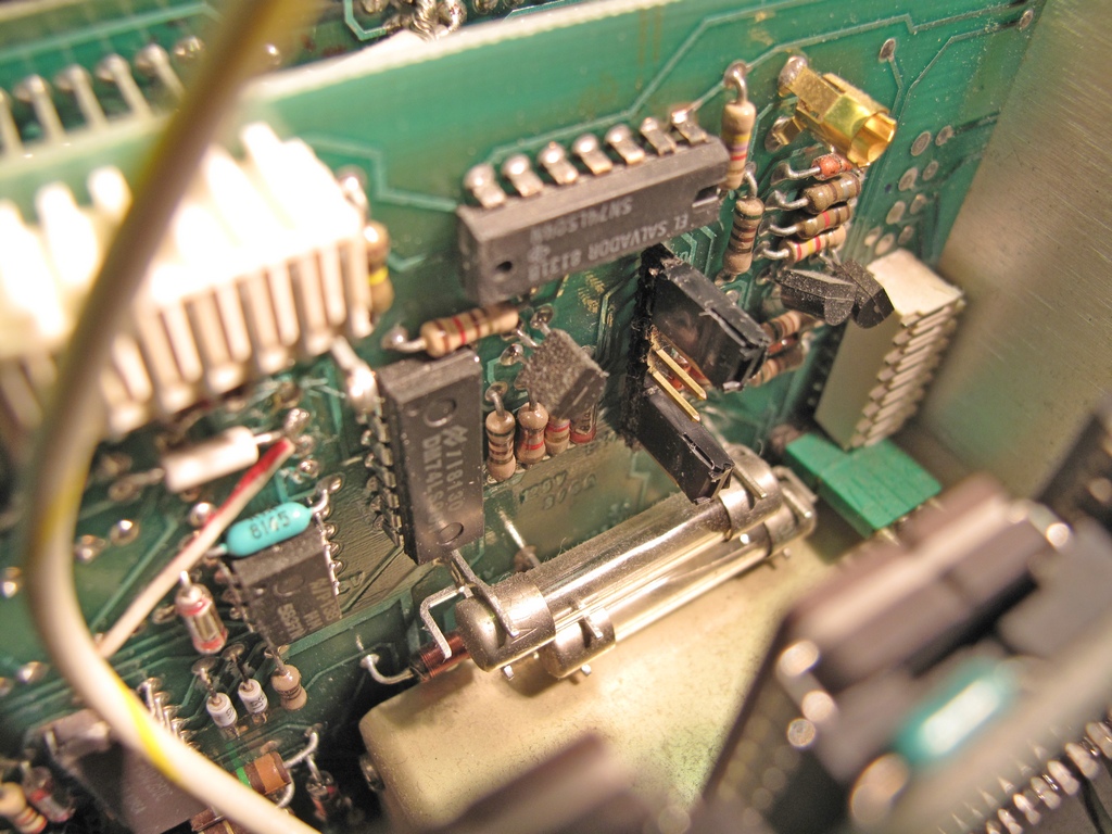
The connector pins with straps. The lower one selects INT or EXT clock and the upper one External Clock frequency (1, 5 or 10 MHz).
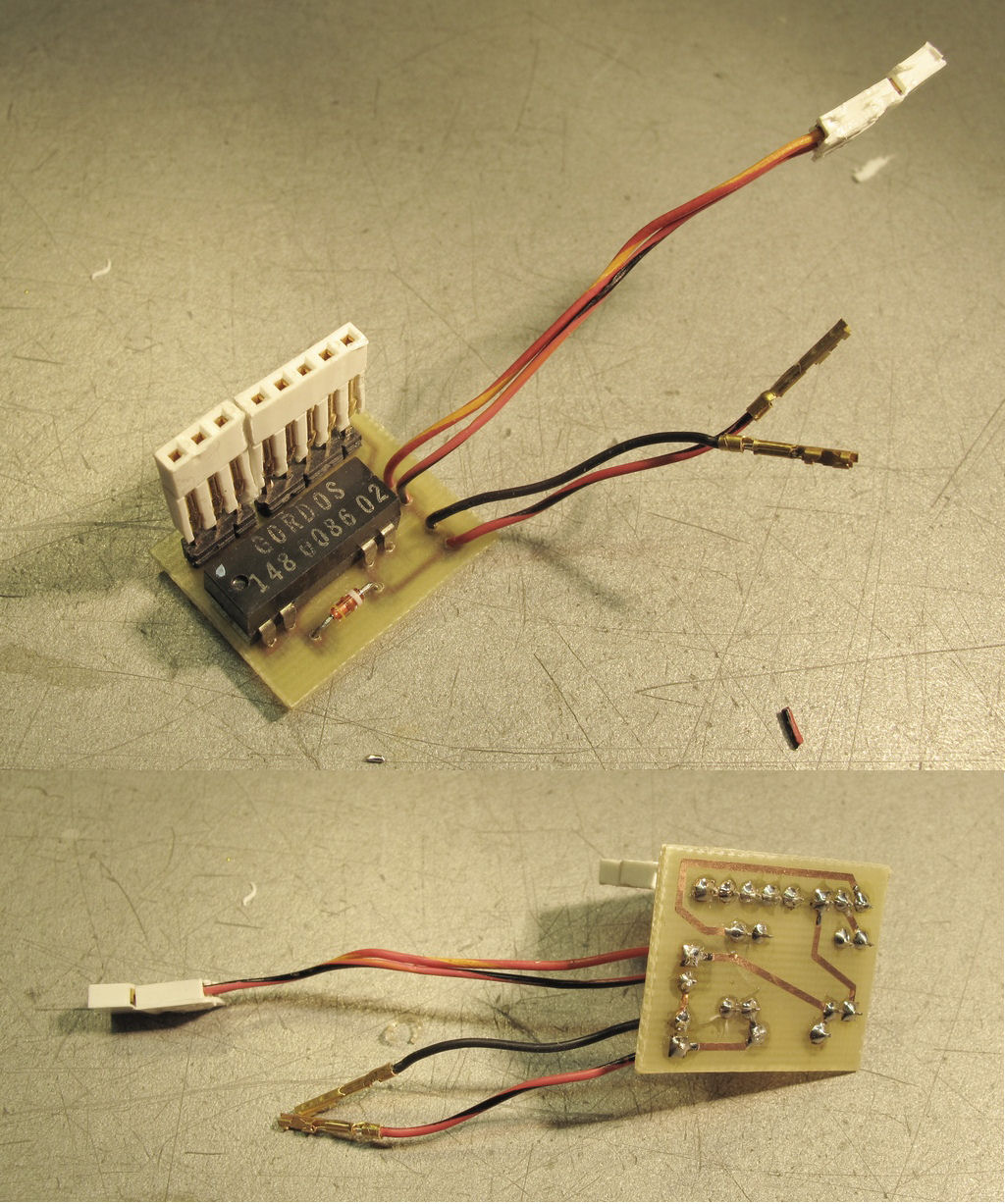
Made a small circuit board which connects directly to the connector pins. It has a reed relay powered from +5V and activated by a switch on the rear panel of
the TM5006 mainframe.
The DC5010 has several free pins on the Rear Interface Connector. There are even some with pads on the board. I choose 23 A & B for the switch.
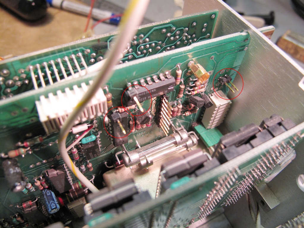
Straps removed and new pins added.
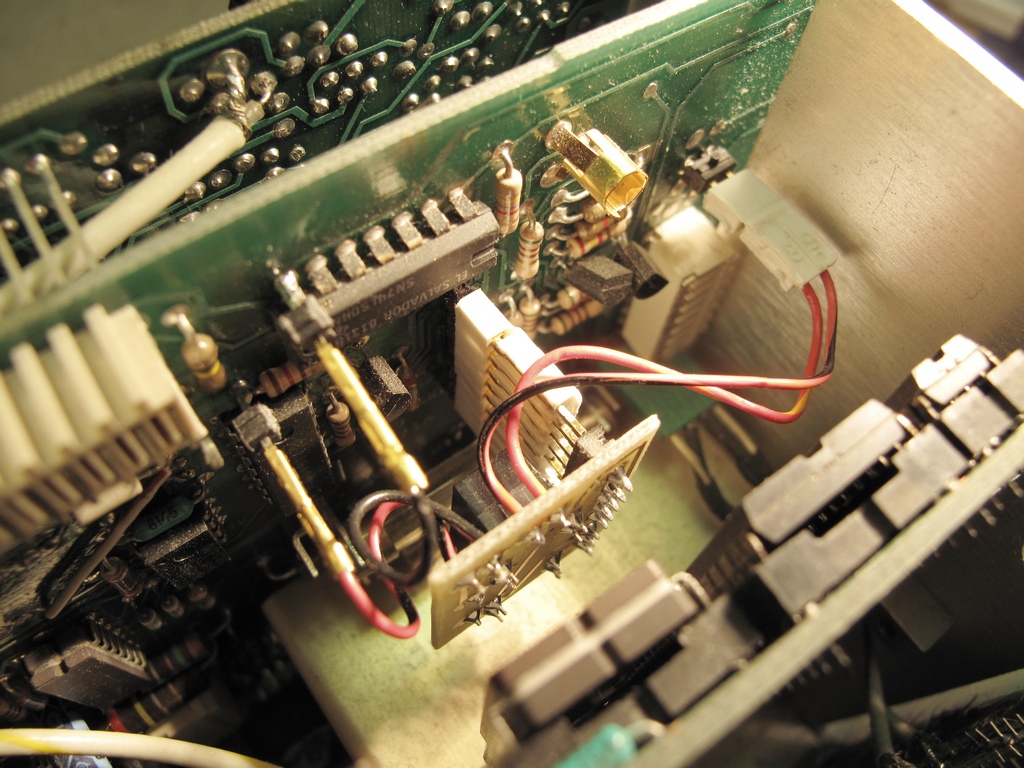
The circuit board in place.
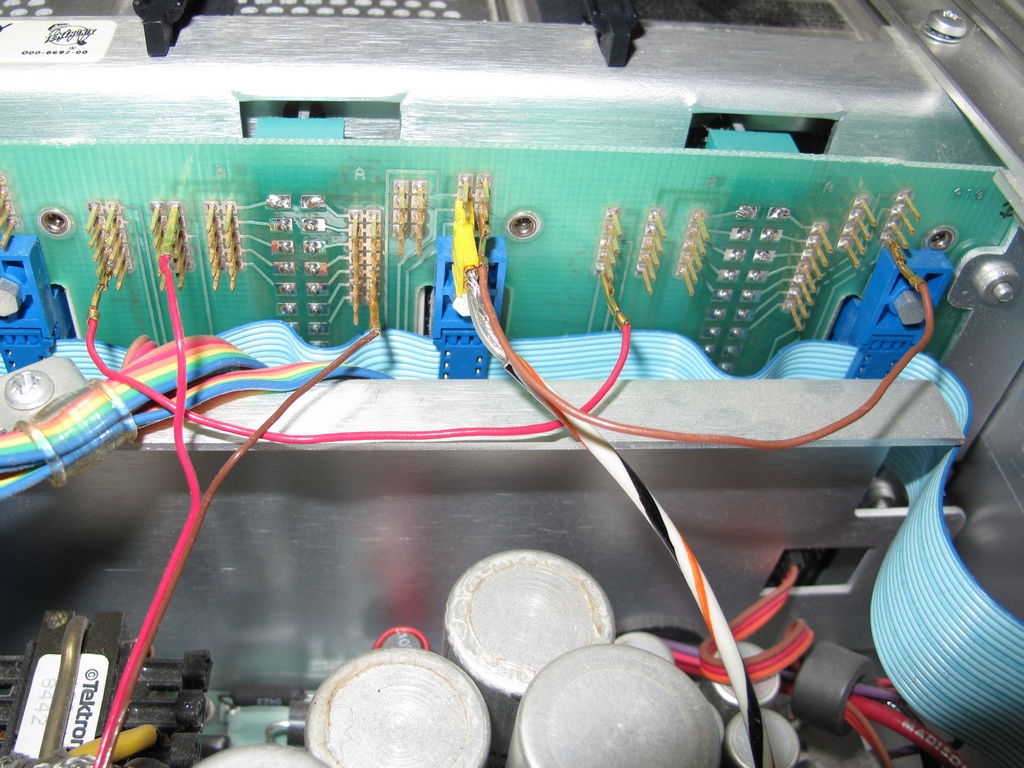
The TM5006 interface seen from the rear. The red/brown wire on the left goes to the switch. The horizontal red and brown wires comes from a DP501 Digital
Prescaler so the DC5010 automatically multiplies the count by 16 when prescaling is used. The coax with yellow connector is the EXT Clock input.
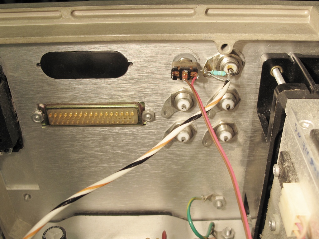
The TM5006 rear panel seen from the inside ...
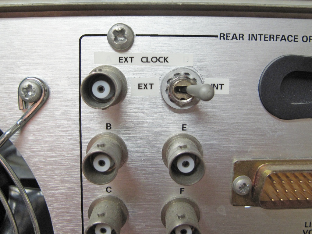
... and from the outside.
Change
Since the above was written and done I moved the switch to the front of the TM5006 and also the terminating 50 ohm resistor from the TM5006 rear panel to inside
the DC5010 (on the relay board shown above).
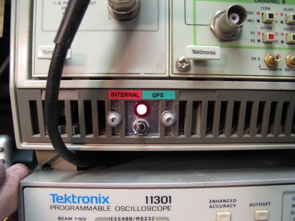
A dual color LED indicates the setting according to the labels.
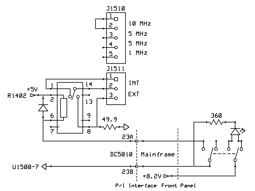
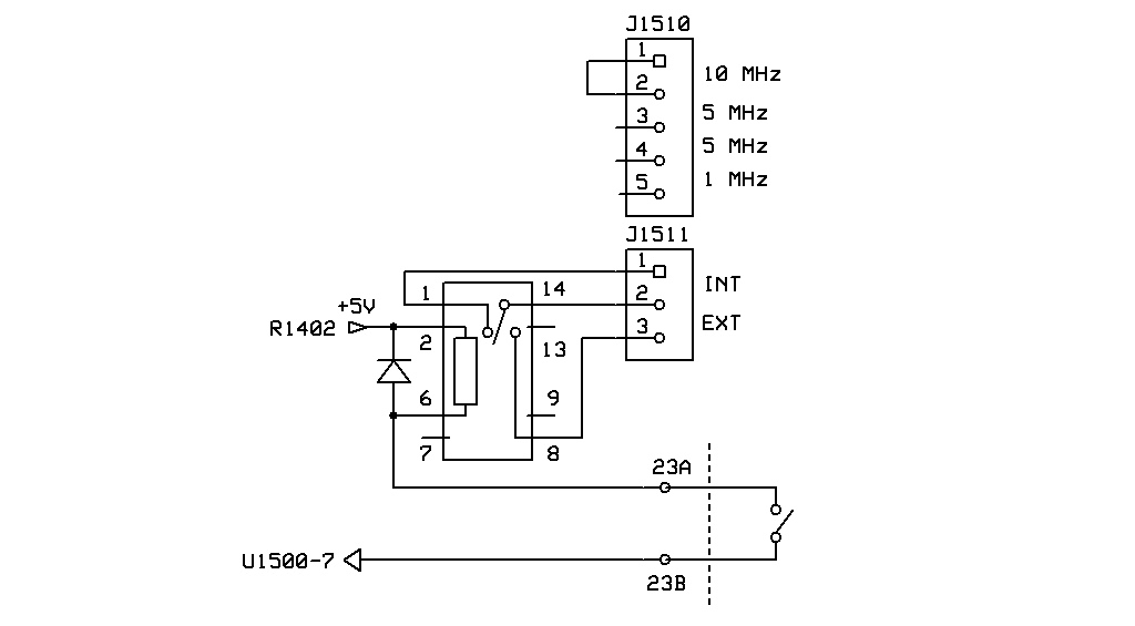
Revised schematic
Email me with comments. /Håkan
Home / Go back