Building another TM500 / TM5000 Mainframe Test Unit
Several years ago I made a very
simple test plug for TM mainframes. Basically the only thing it did was
route the various voltages and transistor pins available on the interface
to the front panel. So inspired by discussions on the Tekscopes forum and seen
what other have done I decided to make another unit, a little more sophistcated
than my old.
These are the functions I wanted:
1: Test that the two 25V AC windings are OK, i.e. there is no short to
ground and that the phase between them is correct.
2: Show DC voltages on a digital display.
3: Show AC voltages on a digital display.
4: Momentary load the
selected DC voltage with about 0.5A and show DC voltage and AC ripple at the same time.
5: Output the selected voltage to the front panel for a more accurate reading on
an external DVM.
6: Output the transistor pins to the front panel to be
viewed on a Curve Tracer.
Many areas on the pictures below can be clicked to show a close up.
The donor plug this time was this one. I had no idea what it is for and it contained no active parts so only the mechanical part could be used.
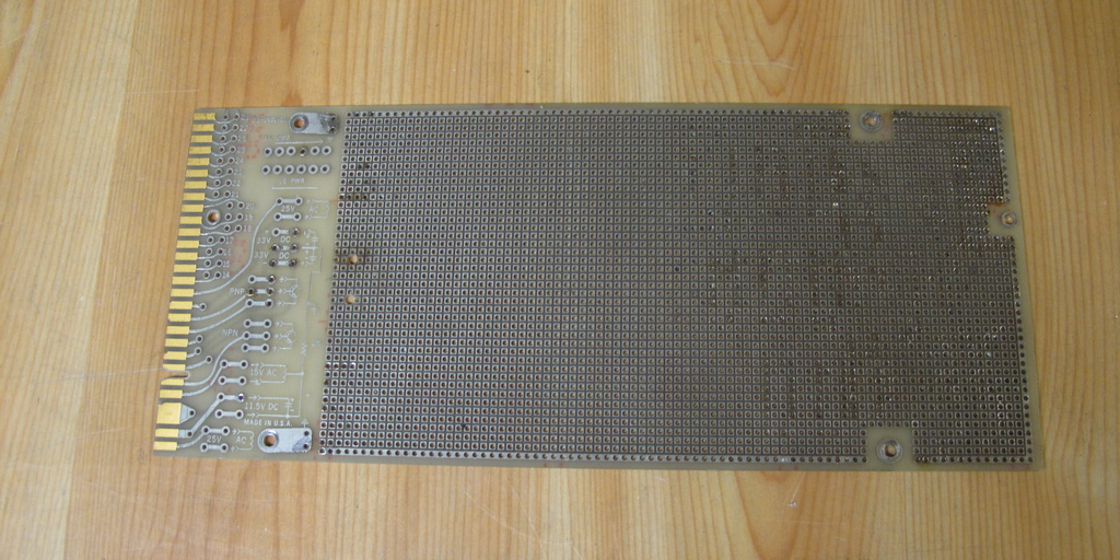
Since the donor didn't have an
interface connector and I needed access to all voltages and the transistors I
used an original board from a blank plug kit.
The new plug had to have boards
on both sides of the board so I could only use the interface connector since the
original board is not at the center of the plug.
I sawed it
off a bit to the right of the mounting holes in the first vertical column of
holes and then, as before, made an aluminum subframe with enough offset
to
accomodate boards on both sides.
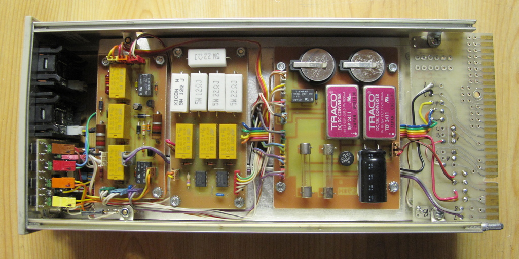
The
right inside: Float/Phase board, Load board and Power supply board. The
power to meters and all boards originates from the 17.5VAC winding and the
rectified 5V is grounded in the
chassi. Since the digital meters can only show positive voltages the negative
voltage had to reversed so the power to the meters
had to be floating therefore I
used a TRACO DC-DC converter with floating output. The 17.VAC winding is center
tapped to ground via a 1k resistor in TM500
mainframes but in TM5000
mainframes it is hardwired directly to ground which I found out the hard way.
Therefore the second TRACO DC-DC converter instead
of a simple 7805. The batteries are for the Float
test of the 25VAC windings which is done with power off. This test is off
course is disabled when power is on.
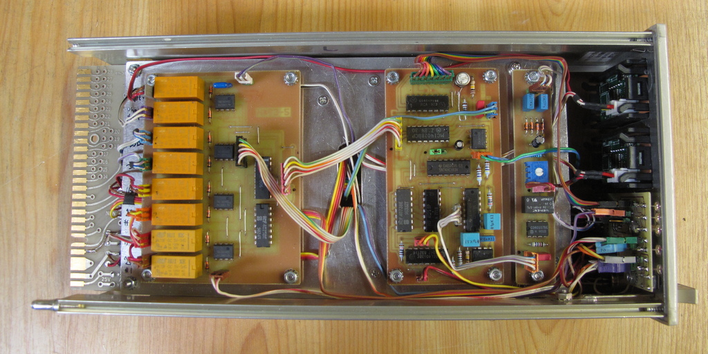
The
left side: Relay board, Control board and AC-to-DC board. I didn't use
the original pull tab and latch since I see no reason to have those in a plugin
that will
be moved in and out all the time. Instead I
used a pull tab from a 7k plugin with a modified release bar screwed directly to
the frame.
Aug 2024 change: The AC-to-DC
board was redesigned to Schottky diodes for the rectifier instead of common
1N4148 diodes.
Also all components except for the variable resistor, relay
and IC are now SMD on the bottom side of the board.
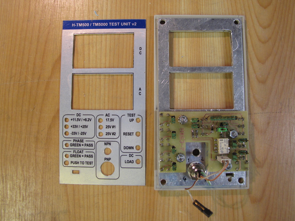
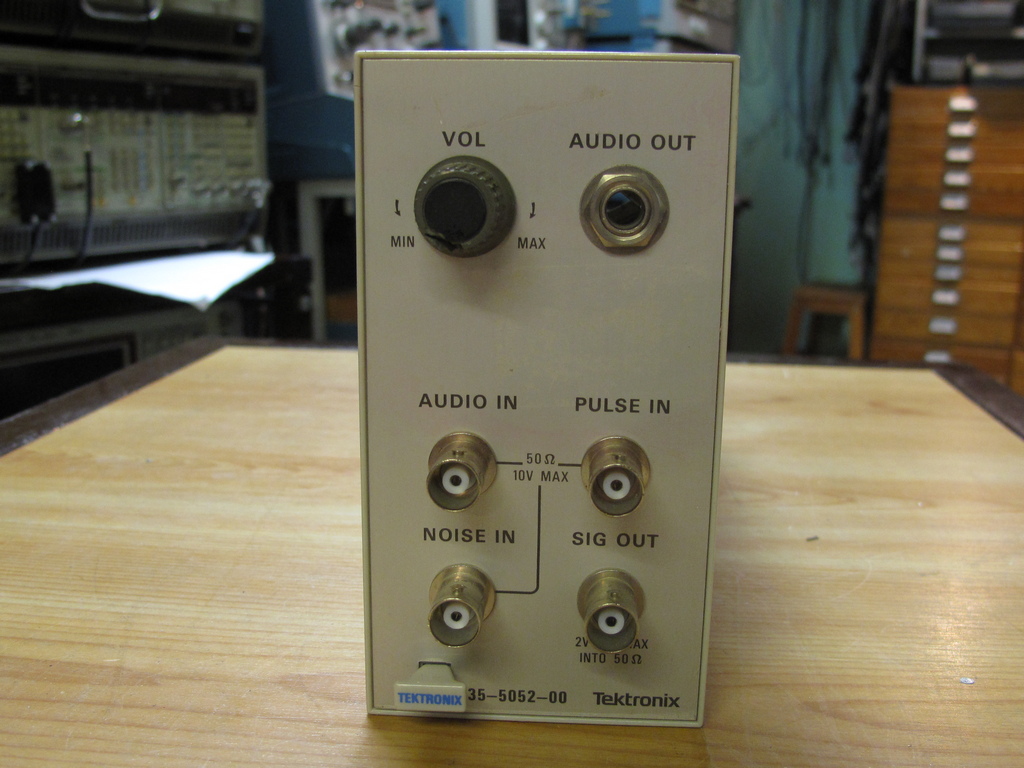
Front
Panel and Front Panel board The round connector on center bottom is
a 4 pole LEMO connector which outputs the transistor pins or the currently
displayed voltage to the CT
interface pod. The green jumper just above the small relay selects either
transistor pins to the output all the time or only when
power is off and the measurements
when power is on.
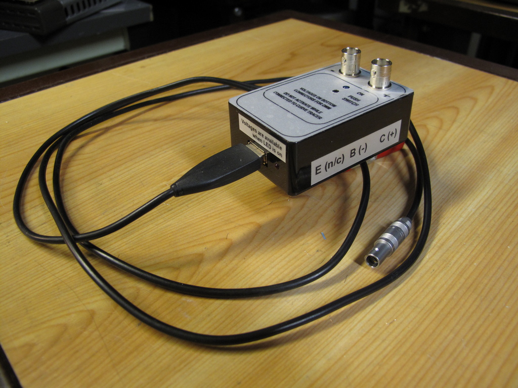
The CT
interface pod: It uses a USB connector and a modified USB cable to
connect to the front panel. While power is on and measurements are enabled on
the
front panel board the selected
measurement is available on the the BNC connectors for a differential scope or
DMM cables. The measurements could be routed
to the C and B connectors so the
pod could be connected directly to the DMM by pressing the switch in the hole.
In that case E is disconnected from GND and
the condition will remain until
it is powered off. If measurements are not enabled on the front panel board or
the power is off the mainframe's transistor pins are
available on the E, B and C
connectors.
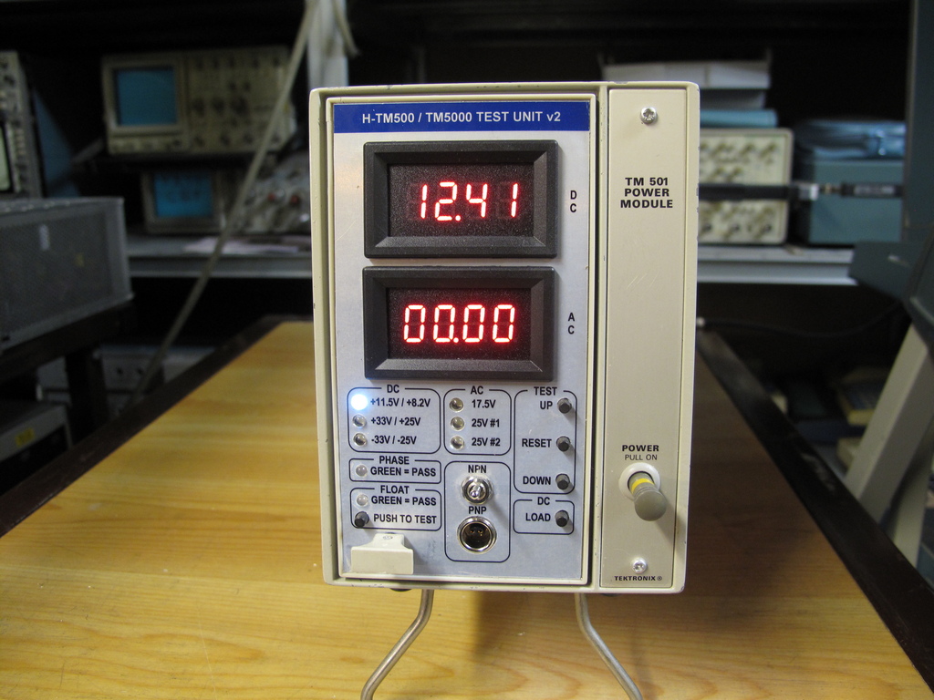
The finished unit testing a TM501. Click on it for a short video.
Schematics, parts List and layouts of all boards here.
TM500 Mainfrmae Test unit TM5000 Mainframe Test unit TM500 Mainfrmae Tester TM5000 Mainframe Tester
Email me with comments. /Håkan
Home / Go back