Installing an LCD display in a TDS784A
I used pretty much the same way as I did with the TDS544A but with some changes.
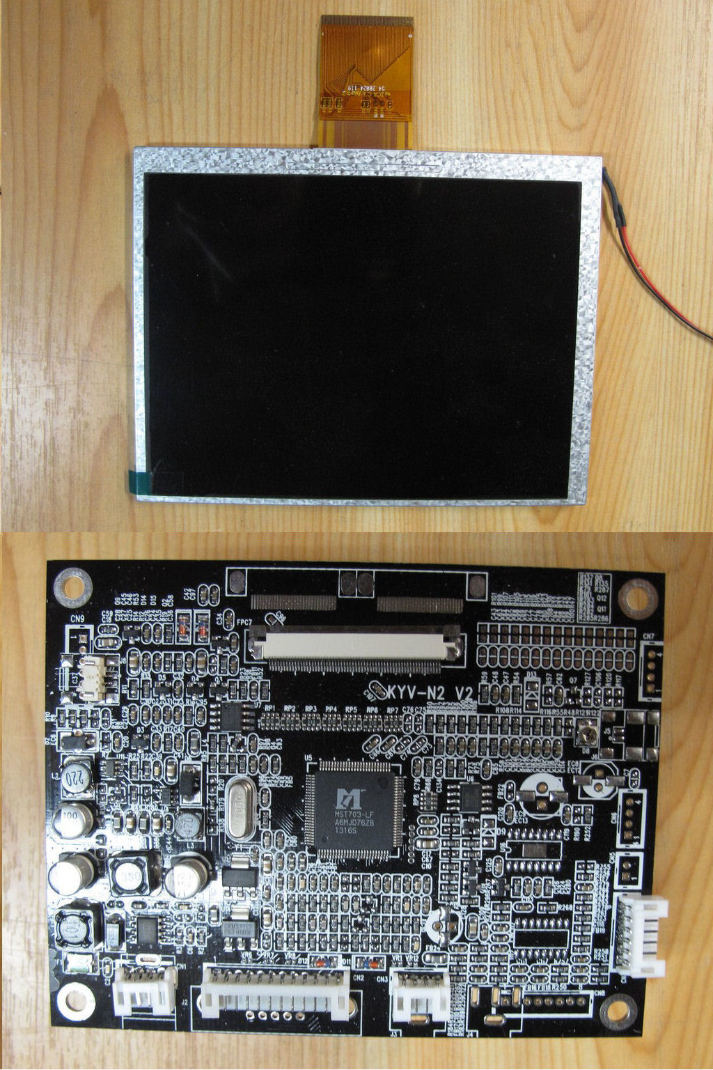
The LCD kit purchased from eBay. There is also a small circuit board with control switches, not shown here.
I used the same LCD kit as the one I used in the TDS544A. There is also another LCD kit available from the same eBay seller which is about $20 cheaper.
It has the flex cable coming out closer to the side instead of in the center which makes it a little harder to place the driver board. It could be done using an
extension board and cable. Also the display can't be rotated so the cable has to come out at the bottom instead of at the top.
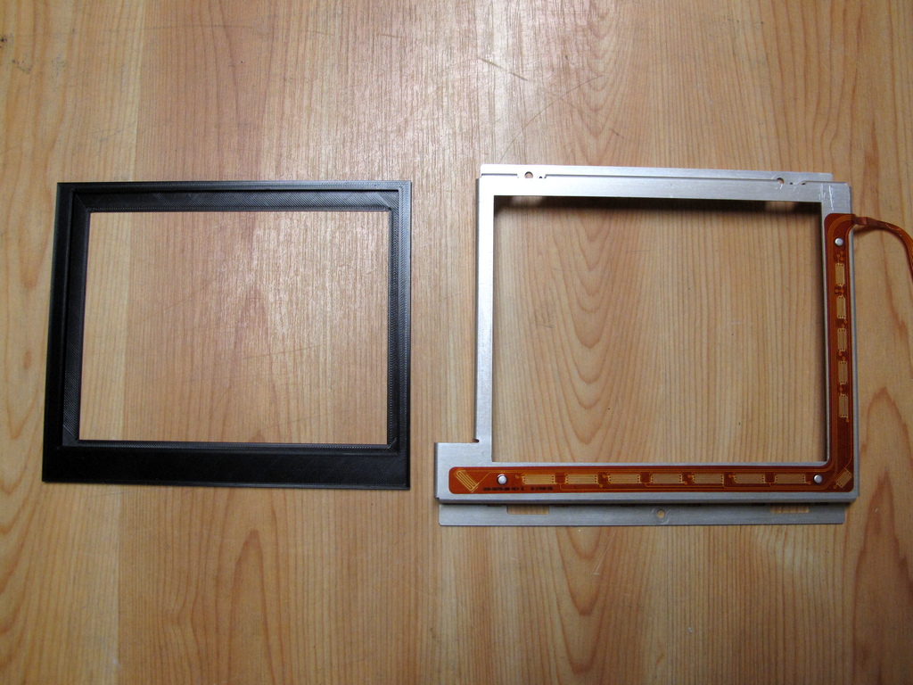
Instead of the thin aluminum I had it 3D printed this time.
I made both versions, i.e. cable coming out at the top and cable coming out at the bottom. I went for the one with the cable at the top.
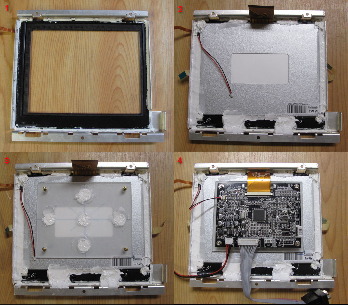
I used neutral cure RTV silicone to secure all hardwares instead of epoxy that I used for the TDS544A. It is less messy and I guess it would be easier to remove if that should ever be needed.
1: The 3D printed holder attached to the aluminum bezel.. It is slightly smaller than bezel edges so it can be exactly aligned to the bezel.
2: The display attached to the 3D printed holder. The edges are slightly larger than the display so it could be exactly aligned to the holder.
3: Cicuit board holder attached.
4: The finished assembly with circuit board and wires attached.
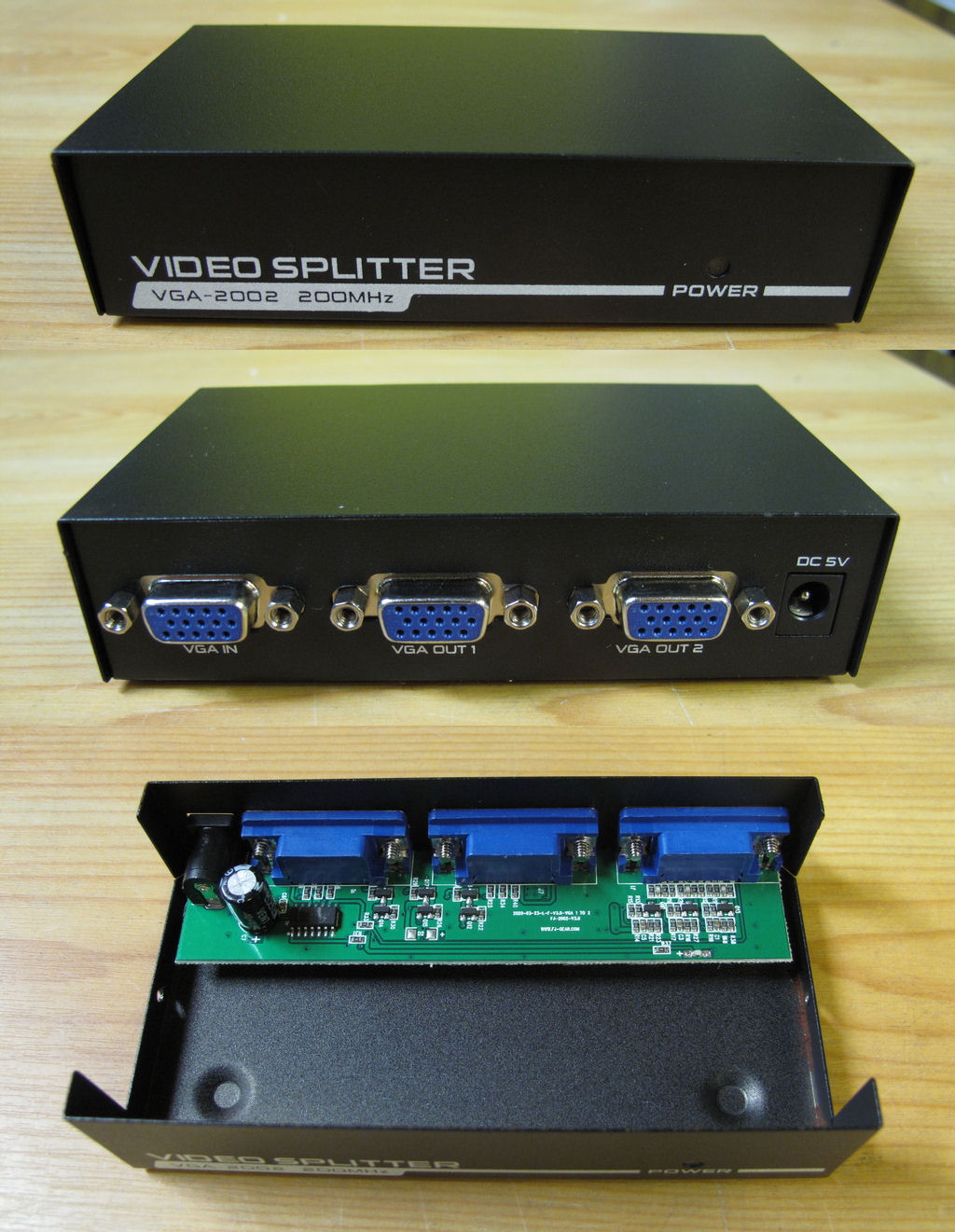
The LCD assy uses the VGA signal from the scope. In order to preserve the VGA output on the rear I purchased a VGA splitter, this time from Aliexpress.
It is similar to the one I used in the TDS544A but not exact the same. The main differences are the lack of mounting holes needed to mount outside its case
and that it runs at +5V. The one in the TDS544A needed +9V.
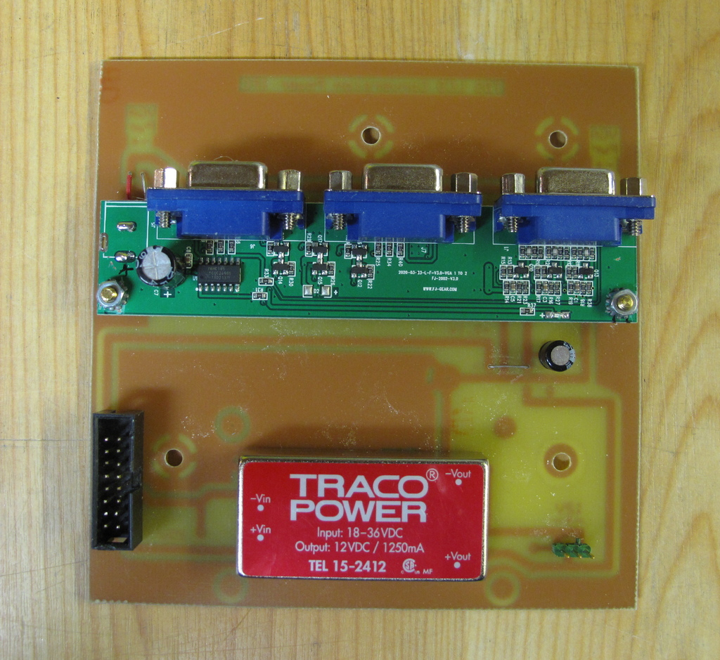
Made a circuit board which
connects to the original mounts in the TDS scope. It also have the power input
connector in the same location as the original CRT
driver board. This is a
slight redsign of my original board that was used in the TDS544A. It has holes for different Step Down converters
and several mounting
holes for different VGA splitters. It uses the +25V in
and outputs +12V to the LCD driver. In case the VGA splitter runs on +5V the
scope's own voltage can
be used from the IDC header. If the VGA splitter
must have a voltage other than +5V or +12V there is room for a 78xx voltage
regulator. If not used the
78xx output on the board must be strapped either to +5V or +12V. There was enough
room on the splitter board to drill holes for the mounting screws.
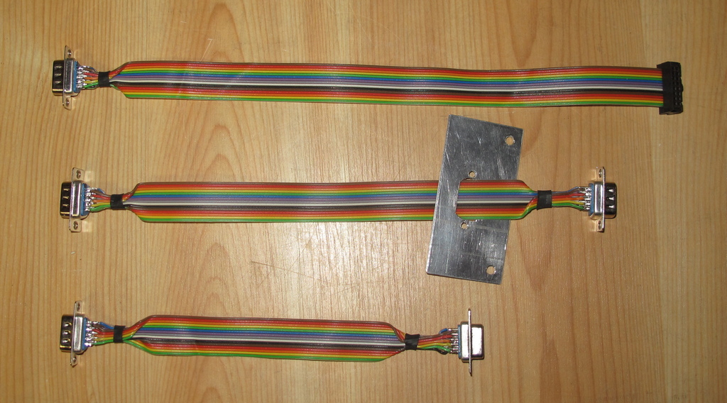
Three special cables had to be
made. The bracket on the one in the middle connects to the front of the scope
close to the LCD display.
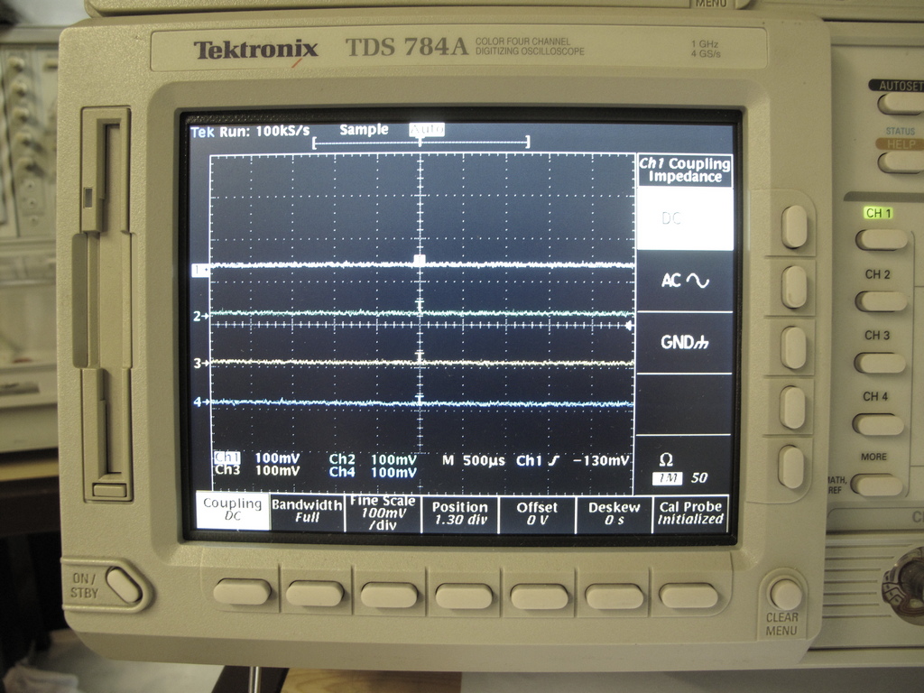
Measurements here.
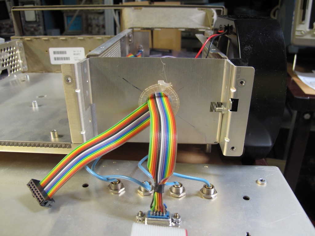
A hole had to be made in the TDS frame in order to route the VGA in and VGA out cables to the splitter.
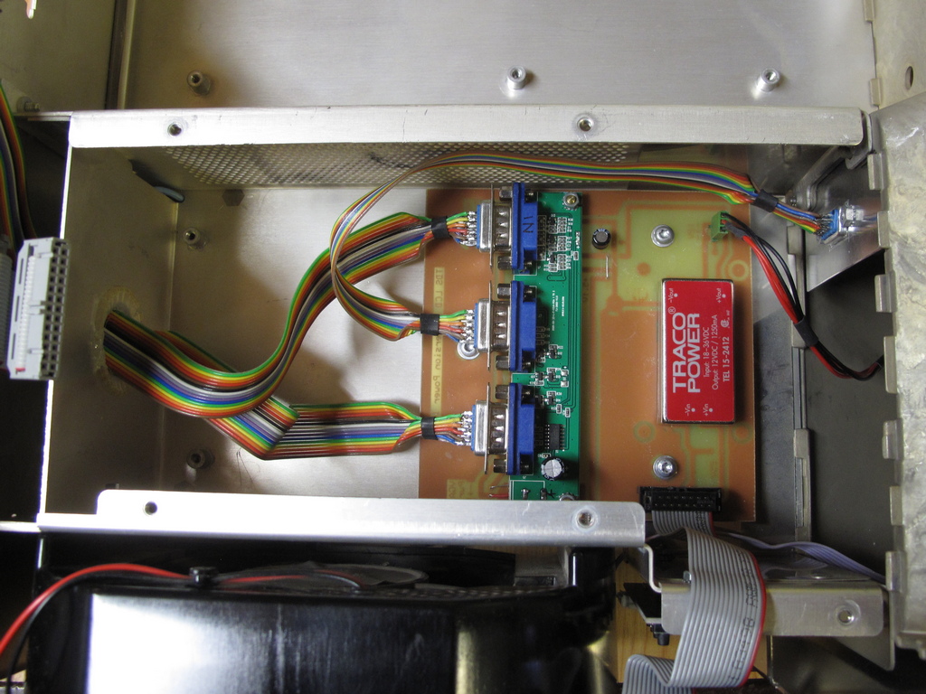
The circuit board, cables and bracket in place.
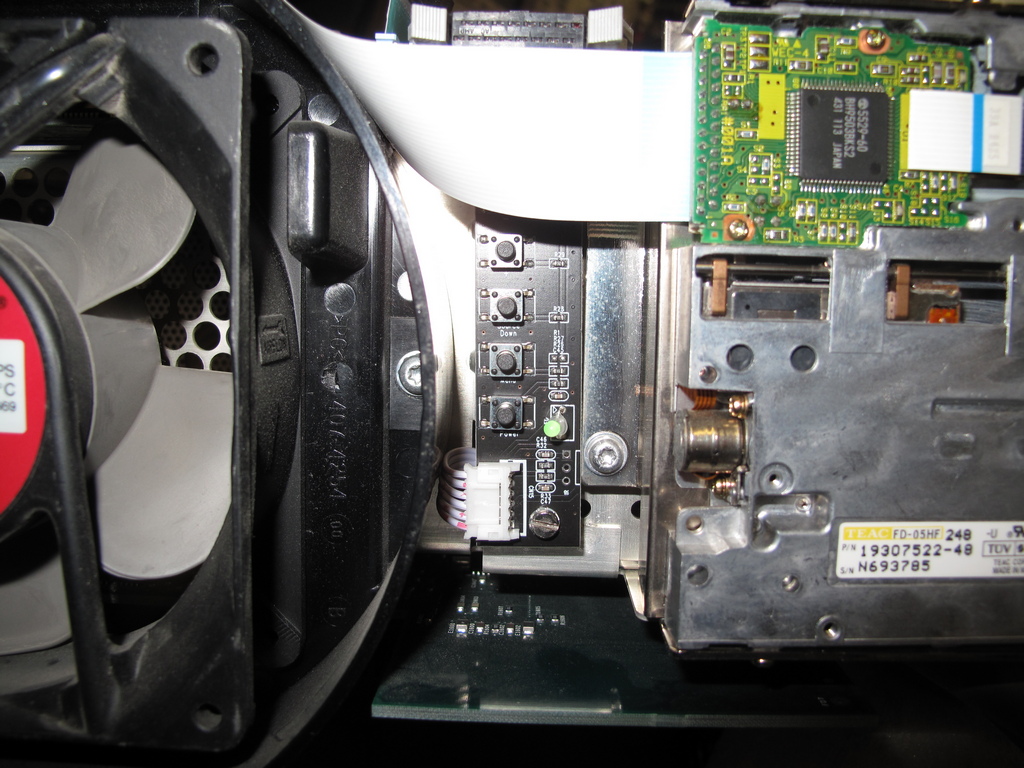
The small control board could fit between the fan and the floppy drive using an existing hole for the lower mount. A new hole had to be drilled for the upper
mount.
The finished display. It doesn't line up perfectly with the bezel buttons but good enough.
Email me with comments. /Håkan